The roller reducer motor assembly process is a critical manufacturing procedure in the field of mechanical power transmission. This process integrates the roller reducer, a compact gear system, with a motor to deliver precise torque and speed control in various industrial applications, including robotics, automation, conveyor systems, and machine tools. The following outlines each key stage in assembling a roller reducer motor, ensuring optimal performance and longevity.
1. Preparation and Component Inspection
Before the actual assembly begins, a thorough inspection of all components is conducted. This includes the motor, roller reducer housing, planetary gears, needle bearings, shafts, seals, fasteners, and lubrication systems. Each part is checked for dimensional accuracy, surface finish, and any signs of wear or defects. Precision is critical at this stage to prevent downstream issues during operation. Cleanliness is also paramount—parts must be free from dust, oil, and debris that could interfere with mechanical tolerances.
2. Pre-Assembly Lubrication
Once components are verified, specific parts of the roller reducer are pre-lubricated. This usually involves applying high-performance grease or oil to the gear sets and bearings. Proper lubrication reduces friction, minimizes wear, and ensures smooth operation during initial startup. Care must be taken to avoid over-lubrication, which can lead to overheating or lubricant leakage.
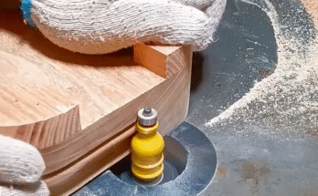
3. Assembling the Gear Mechanism
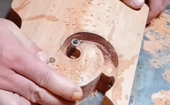
The heart of the roller reducer is its internal gear mechanism, typically comprising planetary gears or cycloidal discs, depending on the design. Assembly begins with fitting the input shaft and output shaft in alignment. Next, needle or roller bearings are inserted into their respective positions, followed by the gear elements.
Precision alignment tools are used to ensure concentricity and axial alignment between the shafts and gears. Even minor misalignments can cause excessive noise, vibration, and premature failure. Once gears are positioned, they are locked into place with circlips or retaining rings.
4. Housing and Sealing
After the gear mechanism is assembled, it is enclosed within the reducer housing. The housing is typically made from cast aluminum, steel, or high-strength composites to ensure structural integrity while minimizing weight. The housing is closed using high-torque bolts, and sealing components such as O-rings or gaskets are installed to prevent oil leakage and to protect against dust and contaminants.
Seals must be placed precisely, especially where the motor shaft enters the reducer. Any compromise in sealing can lead to lubricant degradation and internal contamination, shortening the motor’s lifespan.
5. Motor Mounting
With the roller reducer now fully assembled, the motor is prepared for integration. Motor mounting typically involves aligning the motor shaft with the input shaft of the reducer. This can be accomplished through a direct coupling (rigid or flexible), or by using a flange-mounting method.
During alignment, care is taken to ensure minimal runout and no axial preload on the motor shaft. Misalignment can lead to increased energy consumption, vibration, and bearing failure. In some applications, torque limiters or dampers are also installed between the motor and reducer to absorb shock loads.
6. Fastening and Final Torque Application
Once the motor is mounted, all fasteners are torqued to specification using calibrated torque wrenches. The correct torque values are crucial to maintaining mechanical integrity without damaging the threads or components. Fasteners are typically secured in a cross-pattern to ensure even pressure distribution across mating surfaces.
Thread-locking compounds may also be applied to critical fasteners to prevent loosening due to vibration during operation.
7. Testing and Quality Assurance
After assembly, the entire roller reducer motor unit undergoes rigorous testing. Tests typically include:
- Noise and vibration analysis
- Torque output verification
- Backlash measurement
- Temperature monitoring during operation
- Seal integrity checks
Any deviations from acceptable performance standards are addressed immediately, often requiring disassembly and rework.
8. Packaging and Documentation
Once the unit passes all quality checks, it is carefully cleaned, labeled, and packaged. Documentation such as assembly reports, inspection certificates, and maintenance guidelines are included to ensure proper installation and operation by the end user.