In the world of precision cutting, stability and dust management are paramount. Vacuum-integrated cutting machines offer a revolutionary solution, securely holding your material while simultaneously whisking away debris. This guide will walk you through the essential steps to harness the power of this advanced hardware.
Step 1: Unboxing and Initial Assembly (The Foundation)
Before you can make your first precise cut, proper assembly is crucial.
- Unpack with Care: Carefully remove all components from their packaging. Check against the packing list to ensure everything is present and undamaged.
- Frame Assembly: Follow the manufacturer’s instructions to assemble the main frame and gantry structure. This is often the largest and most critical part of the setup, ensuring the machine’s rigidity and accuracy.
- Leveling the Machine: Use a spirit level to ensure the machine’s base is perfectly level. This prevents twisting and ensures consistent cuts across the entire work surface. Adjust leveling feet as needed.
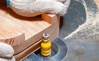
- Mounting the Cutting Head/Spindle: Securely attach the cutting head (e.g., router spindle, laser head, knife cutter) to the gantry. Ensure it’s properly aligned and tightened according to specifications.
Step 2: Integrating the Vacuum System (The Secure Hold)
The vacuum system is the heart of material stability for these machines.
- Vacuum Table Installation: Install the vacuum table onto the machine’s frame. This typically involves aligning it with pre-drilled holes and securing it with bolts.
- Connecting Vacuum Hoses/Piping: Connect the vacuum manifold on the table to the external vacuum pump. Ensure all connections are airtight to maximize suction. Use appropriate diameter hoses for optimal airflow.
- Vacuum Pump Setup: Place the vacuum pump in a well-ventilated area, away from the machine if possible, to minimize noise and heat. Connect it to a dedicated power source.
- Testing Vacuum Hold-Down: Before any cutting, perform a test to ensure the vacuum system creates sufficient suction. Place a piece of scrap material on the table and activate the vacuum. It should be firmly held in place. Identify and seal any leaks using gasket material or plugs for unused vacuum zones.
Step 3: Electrical Connections and Software Installation (Bringing it to Life)
This step involves connecting the machine to its power source and installing its operating intelligence.
- Power Connections: Connect the machine’s main power supply and the vacuum pump’s power supply to appropriate electrical outlets. Ensure proper grounding for safety.
- Data Connections: Connect the machine’s control unit to your computer (typically via USB, Ethernet, or dedicated control card).
- Control Software Installation: Install the machine’s control software and any necessary drivers on your computer. This software allows you to send commands and G-code to the machine.
- CAD/CAM Software Setup: Install your Computer-Aided Design (CAD) and Computer-Aided Manufacturing (CAM) software. This is where you’ll design your parts and generate the cutting paths. (Some machines have integrated CAD/CAM functionality).
- Initial Configuration: Follow the software’s prompts for initial machine configuration, including setting up machine dimensions, motor directions, and safety limits.
Step 4: Calibration and Tool Setup (Precision Preparation)
Calibration is key to achieving accurate and repeatable results.
- Homing the Machine: Perform the homing procedure (if applicable), which tells the machine its absolute zero position.
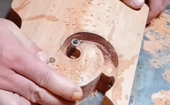
- Z-Axis Calibration (Tool Height Setting): This is critical. Use an automatic tool setter or manual method to accurately define the cutting tool’s zero point relative to the material surface. Incorrect Z-zero leads to wrong cutting depths.
- Tool Installation: Securely insert the appropriate cutting tool (e.g., end mill, V-bit, drag knife) into the spindle collet. Ensure it’s tightened to the manufacturer’s specifications.
- Test Cuts and Fine-Tuning: Run small test cuts on scrap material. Measure the dimensions and inspect the cut quality. Adjust feeds, speeds, and offsets in your CAM software as needed to achieve desired results.
- Material Alignment: Use the machine’s laser pointer or guides to precisely align your material on the vacuum table according to your digital design.
Step 5: Operation and Maintenance (Sustained Performance)
Once set up, consistent operation and maintenance ensure longevity and accuracy.
- Secure Workpiece: Place your material on the vacuum table and activate the vacuum to securely hold it in place.
- Load G-Code: Load the generated G-code from your CAM software into the machine’s control software.
- Start Cutting: Initiate the cutting process. Always supervise the machine during operation. Be prepared to hit the emergency stop button if any issues arise.
- Monitor Performance: Pay attention to cutting sounds, chip evacuation, and overall machine behavior.
- Dust Collection: Ensure the integrated vacuum system or connected dust collector is effectively removing debris. This maintains a clean cutting environment and prevents tool wear.
- Regular Cleaning: After each use (or regularly, depending on usage), clean the vacuum table to remove any debris or residue.
- Routine Maintenance: Follow the manufacturer’s recommended maintenance schedule, which typically includes:
- Lubricating moving parts (linear rails, ball screws).
- Checking and cleaning air filters.
- Inspecting electrical connections.
- Checking belts and pulleys for wear.
- Replacing worn cutting tools.
By meticulously following these steps, you can unlock the full potential of your vacuum-integrated cutting machine, achieving unparalleled precision, cleanliness, and efficiency in your cutting operations.