Motor rings, often components of electric motors or other rotating machinery, frequently require precisely threaded holes for mounting, assembly, or the attachment of other parts. Tapping is the manufacturing process of cutting a screw thread into the inside surface of a hole, allowing for the secure fastening of bolts or screws. The accuracy and quality of these threads are paramount for the overall performance and reliability of the motor assembly.
This guide will detail the meticulous, step-by-step process of tapping holes in motor rings, ensuring strong, clean, and dimensionally accurate threads.
Threading the Future: A Step-by-Step Motor Ring Tapping Process
The tapping process requires careful preparation, precise machine setup, and vigilant quality control to achieve optimal results.
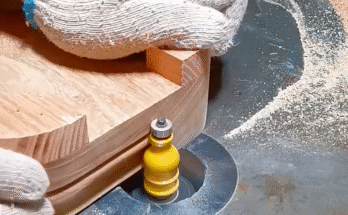
Step 1: Design Review and Pre-Tapping Hole Preparation
The quality of the tapped hole begins with the drilled hole.
- Review Specifications: Thoroughly examine the engineering drawings or specifications for the motor ring. Note the thread size (e.g., M6, 1/4-20 UNC), thread pitch, hole depth, and tolerance requirements.
- Material Analysis: Understand the material of the motor ring (e.g., aluminum, steel, cast iron). This influences tap selection, cutting fluids, and machine parameters.
- Drill Hole Creation: Ensure the holes to be tapped are already drilled to the correct tap drill size. This is a critical dimension; an incorrect drill size will lead to poor thread quality (too loose or too tight).
- Example: For an M6x1.0 thread, a 5.0mm drill bit is typically used.
- Deburring Drilled Holes: Remove any burrs from the drilled hole edges. Burrs can interfere with the tapping process, damage the tap, or create an inconsistent thread start. Chamfering the hole entrance is often recommended.
- Cleaning: Ensure the drilled holes are clean and free from chips, oil, or debris.
Step 2: Tap Selection and Tooling Setup
Choosing the right tap and setting up the machine correctly are crucial.
- Tap Selection:
- Type: Select the appropriate tap type (e.g., hand tap, machine tap, spiral flute, spiral point, form tap) based on the material, hole type (through-hole or blind hole), and production volume.
- Material: Ensure the tap material (e.g., High-Speed Steel (HSS), Cobalt, Carbide) is suitable for the motor ring material.
- Coating: Consider coatings (e.g., TiN, TiCN) for extended tool life and improved chip evacuation.
- Machine Setup:
- Tapping Machine/Drill Press: Use a dedicated tapping machine, a CNC machining center, or a drill press equipped with a tapping attachment.
- Workholding: Securely clamp the motor ring in a vise or fixture. The clamping must be rigid to prevent movement during tapping, which could lead to tap breakage or misalignment.
- Alignment: Ensure the tap is perfectly aligned with the drilled hole. Misalignment is a common cause of tap breakage and poor thread quality.
- Spindle Speed and Feed Rate: Set the correct spindle speed (RPM) and feed rate (for machine tapping). These parameters are critical and depend on the tap size, material, and tap type. For rigid tapping on a CNC machine, the feed rate is directly linked to the pitch of the thread.
Step 3: Lubrication and Cutting Fluid Application
Proper lubrication is essential for smooth tapping and tap longevity.
- Cutting Fluid Selection: Choose a cutting fluid specifically designed for tapping the motor ring’s material. This fluid reduces friction, dissipates heat, and aids in chip evacuation.
- Application: Apply the cutting fluid generously to the tap and into the drilled hole before and during the tapping process. For automated systems, ensure the coolant system is functioning correctly and delivering fluid to the cutting zone.
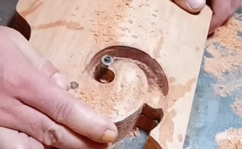
Step 4: The Tapping Operation
This is where the threads are cut.
- Manual Tapping (for low volume/large threads):
- Insert the tap into the hole, ensuring it’s straight.
- Apply light, even downward pressure.
- Turn the tap wrench clockwise (for right-hand threads) for a half to one full turn.
- Turn the tap wrench counter-clockwise for a quarter to half turn to break the chip.
- Repeat until the desired depth is reached.
- Machine Tapping (most common for production):
- The machine automatically advances the tap into the hole at the programmed feed rate and speed.
- For blind holes, the machine will reverse the tap automatically once the programmed depth is reached.
- Ensure chips are evacuating properly. If chips are binding, adjust parameters or consider a different tap type.
Step 5: Chip Evacuation and Hole Cleaning
Efficient chip removal prevents tap damage and ensures thread quality.
- During Tapping: The design of the tap (e.g., spiral flute for blind holes, spiral point for through-holes) aids in chip evacuation. Cutting fluid also helps flush chips away.
- Post-Tapping Cleaning: After tapping, thoroughly clean the newly threaded hole to remove all chips and cutting fluid residue. This can be done using compressed air (with caution and appropriate PPE), brushes, or flushing with cleaning solutions. Residual chips can interfere with subsequent assembly.
Step 6: Quality Control and Inspection
Verify the quality and accuracy of the tapped threads.
- Visual Inspection: Visually inspect the threads for completeness, smoothness, and any signs of damage or torn threads.
- Thread Gauge Inspection: Use Go/No-Go thread gauges to verify the thread’s pitch diameter and overall form. The “Go” gauge should thread in smoothly, and the “No-Go” gauge should not enter more than 1.5 to 3 turns (depending on standard).
- Depth Measurement: Verify the tapped depth, especially for blind holes, to ensure it meets specifications.
- Torque Testing (if applicable): For critical applications, perform torque testing with a mating fastener to ensure proper thread engagement and strength.
Step 7: Post-Tapping Processes (Optional)
Further processing may be required for the motor ring.
- Deburring: Remove any minor burrs that may have formed at the hole exit during tapping.
- Surface Treatment/Coating: If the motor ring requires plating, painting, or other surface treatments, ensure the threaded holes are protected or re-tapped if necessary after the treatment.
- Assembly: The motor ring is now ready for assembly with its mating components.
Conclusion
The motor ring tapping process is a testament to precision manufacturing, where the creation of accurate internal threads is vital for the functionality and longevity of mechanical assemblies. By meticulously following each step, from careful hole preparation and tap selection to precise machine operation and rigorous quality control, manufacturers can ensure that every tapped hole meets the highest standards, contributing to the reliable performance of the final product.